RS-485 waveform

Topics about the Hardware of Revolution Pi
Post Reply
songha
Posts: 27
Joined: 02 Jul 2021, 12:48

RS-485 waveform

Post by songha »

Hi all,

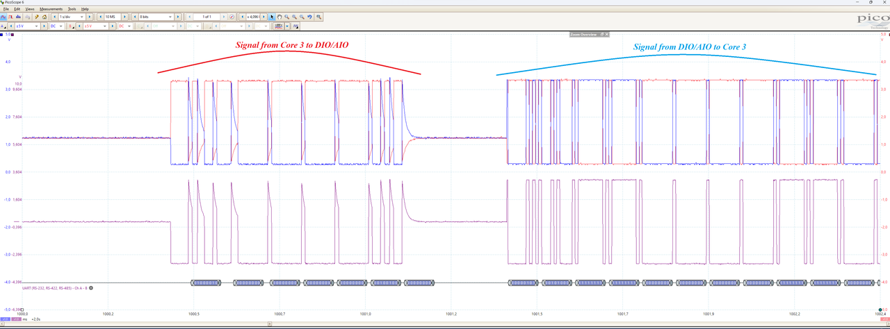
i am doing some tests and measuring the signal RS-485 on the pibridge. My devices are a revpi core 3 connected to an AIO and a DIO on the right side. I use the Picoscope series 5 to measure the signal RS-485 + (blue waveform), RS-485 - (red waveform) and difference of them (purple waveform). The picture below shows my results. As you can see, the signal from the core 3 to the device AIO or DIO looks very strange. It should be rectangular like the signal comes from AIO or DIO to Core 3, but it is not. So when I try to decode the signals with Picoscope, I get the wrong data. Can someone help me to explain it please.

Song
Image
User avatar
dirk
KUNBUS
Posts: 2111
Joined: 15 Dec 2016, 13:19

Re: RS-485 waveform

Post by dirk »

Dear Song, thank you for your detailed analysis and the evaluations based on the sum signal. This is normal as far as I can see (and also a quick test with Oszi confirms this with a Core 3). Signal levels in practice are often not perfect. As long as the thresholds are reached, it still works.
songha
Posts: 27
Joined: 02 Jul 2021, 12:48

Re: RS-485 waveform

Post by songha »

Hi Dirk,

thank you for the quick reply. Yes, I can see now. If I choose the appropriate threshold and hysteresis for decoding, I still get the correct data on the bus. But it is not clear why this not perfect signal occurs. Do the Core 3 and DIO/AIO use different chip for sending and receiving RS-485 data? And why doesn't the Core 3 use the same chip (if the chip is the reason) as the DIO/AIO if it can provide better performance or more correct signals on the bus?

Song
User avatar
dirk
KUNBUS
Posts: 2111
Joined: 15 Dec 2016, 13:19

Re: RS-485 waveform

Post by dirk »

According to the schematics I can see that the Core 3 uses the CM GPIO14/15 pins. The DI/DO/DIO/AIO modules are using the STM32F205 processor for this job.
Post Reply